Preface
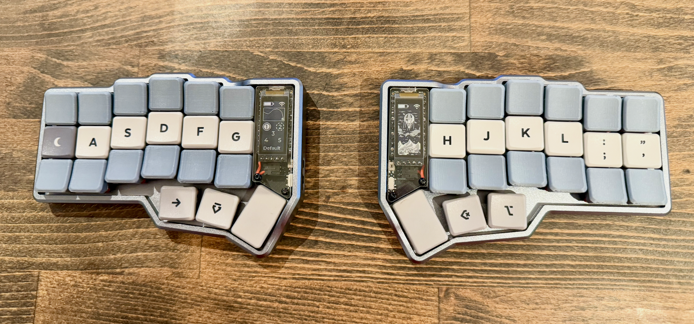
A few weeks ago I made the switch over to using a ergonomic corne-like keyboard. Mostly to combat some wrist pain, and to improve my accuracy typing special characters while programming.
After researching what was available on the market, I decided that the Typeractive Corne had everything that I was looking for. Low-profile, choc spacing, and a beautiful optional premium case. I made the purchase, splurged on the pre-assembled version, and in a few days received the new keyboard.
However, shortly after setting it up, the bottom row on the left half stopped working. I reached out to support (who were fantastic - shoutout Jack) and they shipped me a replacement PCB and nice!nano. I swapped them in, and the keyboard was working again. However, the next day when I went to use it, the entire left half was no longer functional.
I decided that I wanted to get to the bottom of this.
The Problem
After digging around through the Typeractive discord support threads, I found one where someone had experienced a similar issue. In this thread, it was determined that the aluminum case was acting like a capacitor when it wasn’t plugged in - slowly building a static charge. Then, when the user went to connect the device via usb-c cable, the keyboard now had a path to ground causing the case to discharge.
The issue is that the case did not have a dedicated path to ground on the PCB. When it was discharging, the static was taking some path of least resistance through the microcontroller and partially / fully frying it.
The Solution
To solve this issue, a dedicated path from the case to the ground net of the PCB is needed. This allows the static build up to discarge through the USB shield when it is connected, preventing damage to the microcontroller.
The most straight forward solution is to connect a wire from the case to one of the ground pins on the PCB. The easiest way to do this is to use a short piece of wire with a ring terminal on one end. You sandwich the terminal between one of the standoffs of the case and the backplate, with the other end soldered to one of the ground pins on the PCB. This solution was originally implemented by Maba_Kalox here.
This provides a dedicated path for the case to discharge through.
Parts List
Below is a complete parts list of what was used to complete this modification, including the tools.
- Small Files
- M2.2 Lug Plate Solder Ring Terminal Connector
- 2mm Heat Shrink Tubing
- 22 AWG Wire
- Liquid Flux
- Solder (0.6mm)
- Solder Station
- Multimeter
- Wire Stripers
- Soldering Iron
- Gorilla Tape / Hot Glue (Optional)
Walkthrough
Preping the standoffs
Using a small flat file remove the anodization from the top of the case standoff closest to the thumb cluster. Once removed, confirm that no filings are left in the case or standoff threads. Using some compressed air to blow out the area is useful here. Do this to both halves of the case.
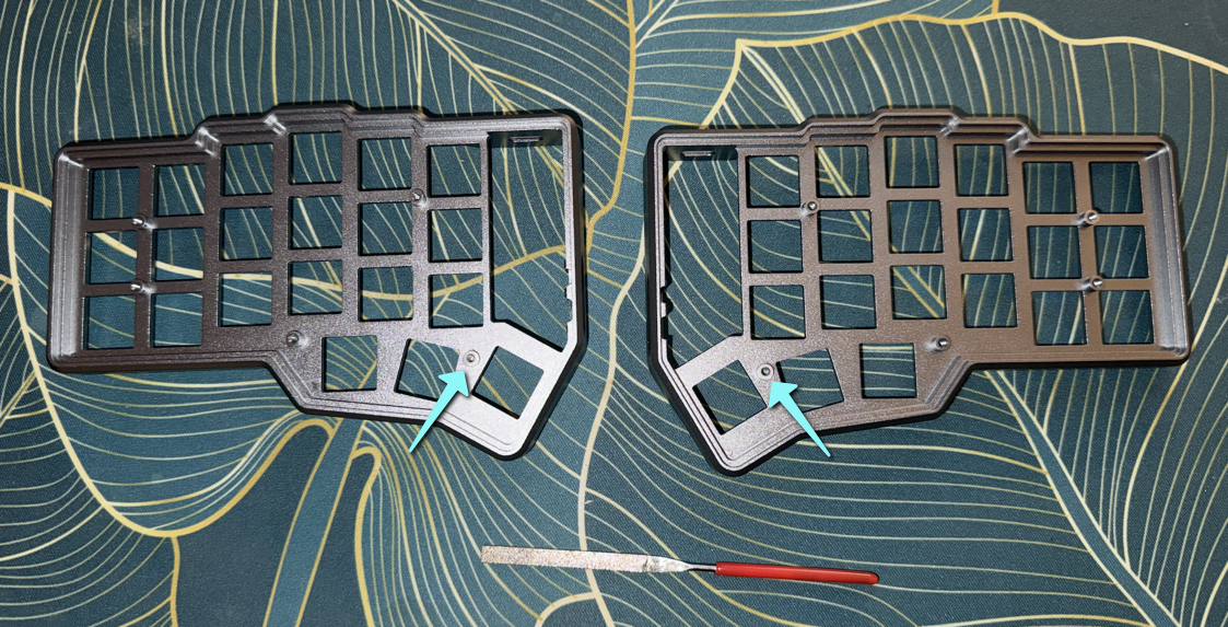
Note: It’s difficult to see it here as I have the graphite coloured case, and the bare aluminum looks similar. I promise the anodization from the top of those standoffs has been filed off.
Making the connector wires
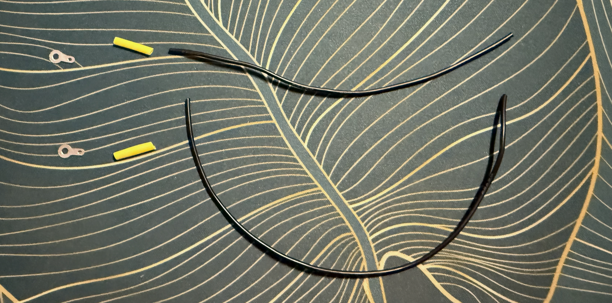
Each of the connector wires is comprised of 3 parts:
- M2 Ring Terminal
- ~12cm piece of 22 AWG wire
- ~1.5cm piece of 2mm diameter heatshrink
Note: 12cm is longer than required, we will cut to size later.
To assemble the wires perform the following steps:
- Strip ~1.5cm from the end of the wire
- If your wire does not have a solid core, twist the core wires together
- Feed the exposed wire through the small hole on the ring terminal
- Fold the wire on itself, then twist to secure
- Apply a drop of liquid flux
- Solder the ring termial to the wire
- Slide the heatshrink over the new connection and shrink with a lighter
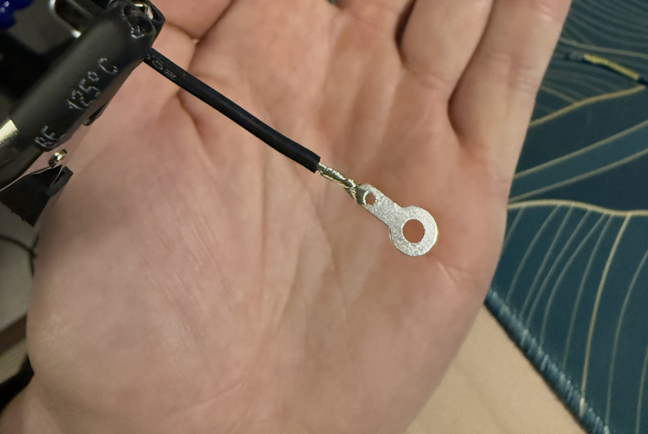
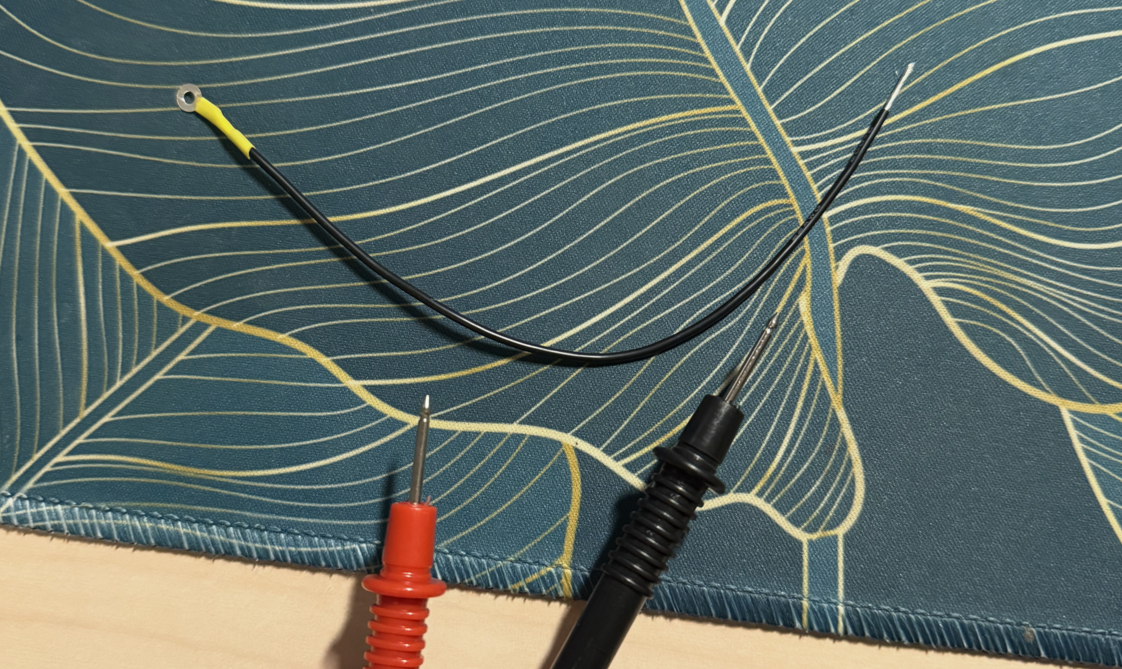
Once you have the terminal connected, I recommend testing for continuity in the wire to confirm a solid connection.
Soldering to the ground pins
Now that the connector cables are assembled, we’re ready to move onto the tricky part, soldering them to the ground pins.
To start, get the connector wire ready to be attached to the pin:
- Cut the connector wire to its final length (mine were approx. 7cm)
- Strip ~2.5mm off of the end of the wire
- Twist the exposed wire, then tin it using solder and flux
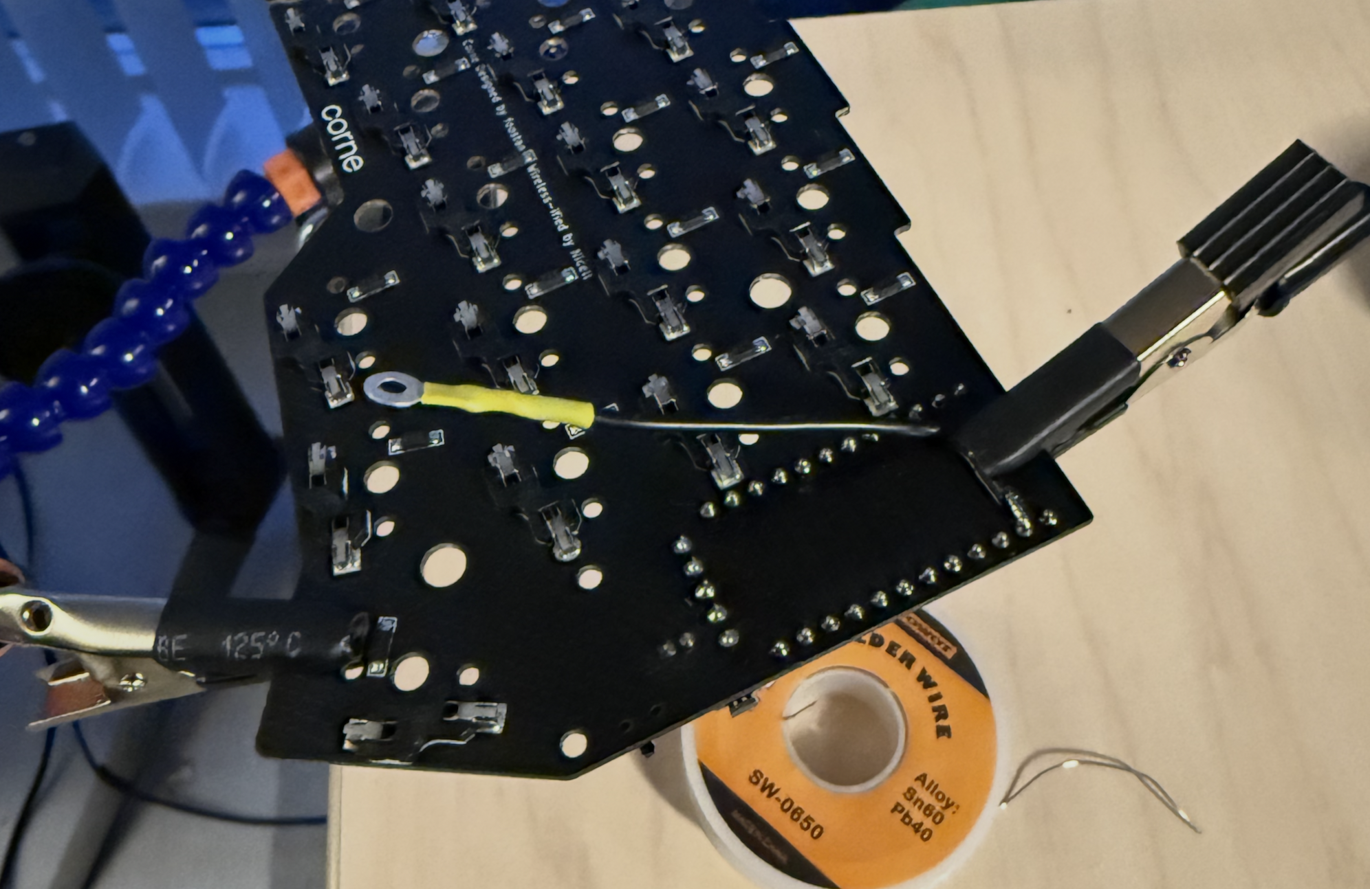
Once this is complete, we can attach it to the ground pin of the board. I found the simpilist way to do this was:
- Position the PCB in the solder station
- Clamp the connector wire directly to the PCB such that the end of the wire is tounching the ground pin
- Add a drop of liquid flux
- Heat with solder iron and apply a small amount of solder
- Once cooled, remove PCB from the solder station. Optionally, strengthen the connection with hot glue or tape. Personally I use Gorilla tape.
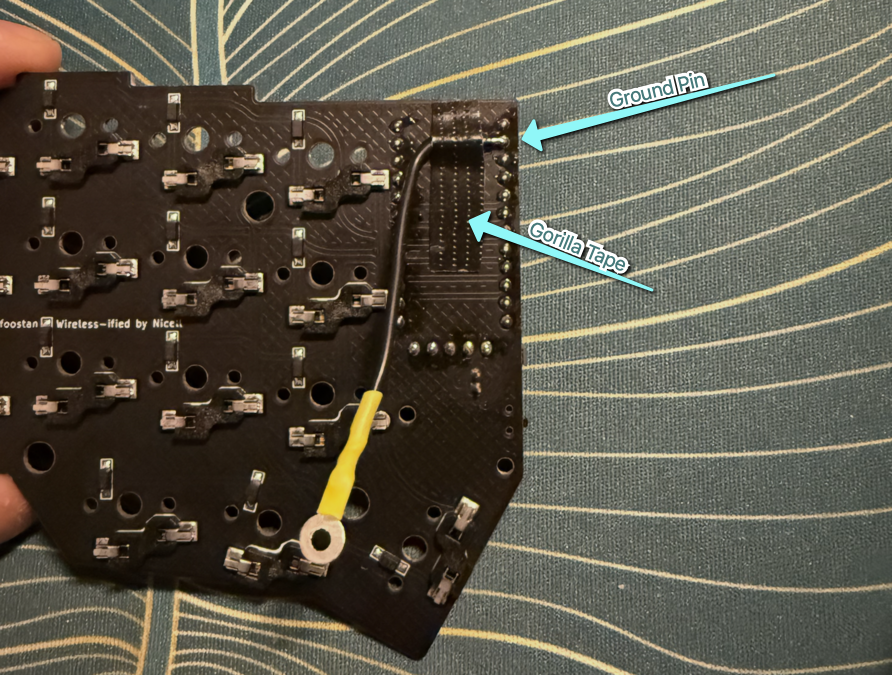
After soldering the connection I recommend verifying the continuity by placeing one of the multimeter probes into the ground pin hole on the PCB, and the other to the ring terminal. You can also use this method to confirm that you havent accidentally bridged to the near by pins, by confirming they don’t have continuity.
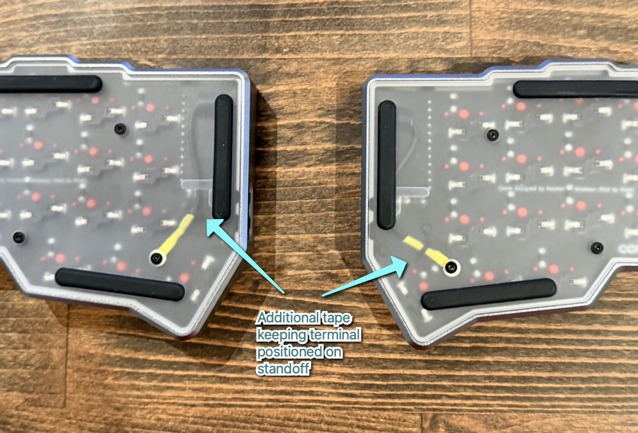
Putting the backplates on
After confirming the continuity I used one more thin piece of Gorilla tape to keep the ring terminals positioned on the standoff. This makes it much easier to put the backplate back on. Once aligned, the backplates can be reattached. Be sure to confirm that the screw connecting to the terminal standoff is passing through the ring terminal.
Repeat this process on both sides, and the modificaton is complete!
Important Tip: This is a reminder that the two corne halves are not mirrors of eachothers. The ground pin locations are not exact same on either side. Before you attempt to solder to the ground pin, triple check that it is infact a ground pin for that half. Fortunately the PCB has all the pins labelled, so its easy to verify.